Mechanics and Kinematics
Mechanics and Kinematics
1. Forward Kinematics
Concept:
Forward Kinematics (FK) is the process of calculating the position and orientation of a robot’s end-effector (e.g., its gripper or hand) based on known joint angles and link geometry.
- Input: A set of joint angles (e.g., 45°, 90°)
- Output: Cartesian coordinates (X, Y, Z) and orientation of the end-effector.
How it Works:
Think of it like giving step-by-step directions:
“From the base, rotate the first joint 45°, extend the second link 30 cm, rotate the next joint 90°, and extend the last link 40 cm.”
Forward kinematics uses mathematics to determine exactly where the end-effector ends up after following these instructions.
It is deterministic — meaning, one input gives one clear output.
2. Inverse Kinematics
Concept:
Inverse Kinematics (IK) does the opposite of FK — it determines the joint angles needed to position the end-effector at a desired target location.
- Input: Desired Cartesian coordinates (X, Y, Z) and orientation.
- Output: The joint angles that achieve that pose.
Why It’s More Complex:
While FK gives a single solution, IK can have:
- Multiple solutions (e.g., “elbow up” or “elbow down”).
- A single solution, or
- No solution if the target is outside the robot’s reachable workspace.
IK is vital for robot path planning, since we usually know where we want the robot to go — not how it must move its joints to get there.
3. Denavit–Hartenberg (DH) Convention
The Denavit–Hartenberg (DH) convention provides a standardized method to assign coordinate frames to each link of a robot manipulator.
This method simplifies describing the robot’s geometry for both FK and IK analysis.
Core Idea
The DH convention represents each link using four parameters, applied in a specific order to relate one joint to the next.
The Four DH Parameters
- Link Length (a): Distance between joint axes (common normal).
- Link Twist (α): Angle between Z-axes of consecutive links, measured about the X-axis.
- Link Offset (d): Distance along the Z-axis between links (variable for prismatic joints).
- Joint Angle (θ): Angle about the Z-axis between X-axes (variable for revolute joints).
The DH Procedure
Assign Frames: Attach a (X, Y, Z) frame to each joint following DH rules.
Determine Parameters: For each pair of frames, find the four DH parameters (a, α, d, θ).
Create Transformation Matrices: Use these to form 4×4 homogeneous transformation matrices for each link.
Multiply Matrices:
Combine all transformations to get the total transformation from base to end-effector:$$ T_{total} = T_{base}^0 × T_0^1 × T_1^2 × \ldots × T_{n-1}^n $$
The resulting matrix gives the position and orientation of the end-effector relative to the base.
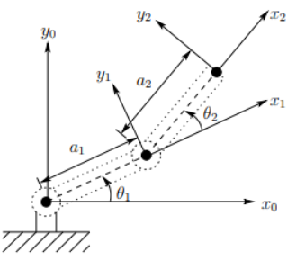
The figure shows a 2-Link Planar Robotic Arm.
The goal is to find the mathematical expressions for the end-effector position (x, y), given:
- Link lengths $ a_1, a_2 $
- Joint angles $ θ_1, θ_2 $
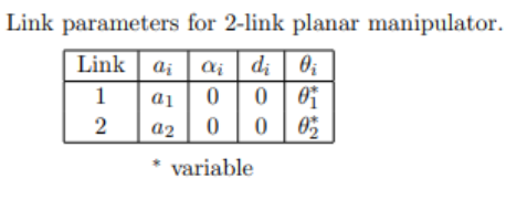
DH Parameter Table
For the 2-link arm, the robot’s geometry can be represented using a DH table:
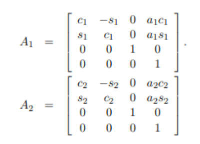
Transformation Matrices
Each link’s transformation is defined by a 4×4 homogeneous matrix, based on its DH parameters:
Composite Transformation
To find the end-effector’s pose relative to the base:
$$ ^0T_2 = A_1 × A_2 $$
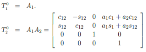
This multiplication results in a composite matrix:
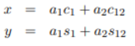
End-Effector Equations
From the composite transformation matrix $ T_2^0 $:
$$
x = a_1 \cos(θ_1) + a_2 \cos(θ_1 + θ_2)
$$
$$
y = a_1 \sin(θ_1) + a_2 \sin(θ_1 + θ_2)
$$
Notation Used in Images:
- $ c_1 = \cos(θ_1) $
- $ s_1 = \sin(θ_1) $
- $ c_{12} = \cos(θ_1 + θ_2) $
- $ s_{12} = \sin(θ_1 + θ_2) $